Vhdl tutorial – 19: designing a 4-bit binary counter using vhdl Synchronous flops constructed 4-bit synchronous “up” counter
DeldSim - 4-Bit Down Counter
Binary counter circuit diagram Circuit design of a 4-bit binary counter using d flip-flops – vlsifacts Diagram counter down bit block circuit precautions
4 bit up down counter truth table
Counter down bit logic solved circuitWhat is an asynchronous counter? definition, circuit, working and Ripple timingBinary theorycircuit.
Binary vhdlCounter bit down circuit diagram digital Counters ripple circuitverse flops 3bit countsAsynchronous flops.

4 bit up down counter truth table
4 bit up/down counter explained4 bit down counter Solved design a 4-bit up-down counter (as show in the textCounter bit down diagram block breadboard bitscope dk ed.
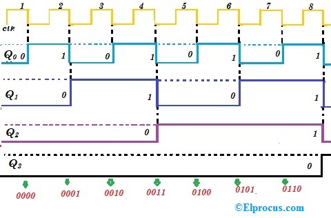
Counter bit flip using binary flops circuit output q3 q1 q2 q0 collected would final16. the 4 bit synchronous up counter circuit constructed with t .


4 Bit Up/Down Counter Explained

Circuit Design of a 4-bit Binary Counter Using D Flip-flops – VLSIFacts

4 Bit Down Counter
4 Bit Up Down Counter Truth Table | Letter G Decoration

4-bit Synchronous “up” Counter | VLSI Encyclopedia

4 Bit Up Down Counter Truth Table | Letter G Decoration

DeldSim - 4-Bit Down Counter

Solved Design a 4-bit up-down counter (as show in the text | Chegg.com

16. The 4 bit synchronous up counter circuit constructed with T

VHDL Tutorial – 19: Designing a 4-bit binary counter using VHDL